VOLTAGE DIVIDER:
Ah yes, the voltage divider -- the foundation for many circuits to come in this learning series. This circuit performs just that, it divides the input voltage down by a specific ratio that is determined from passive components. In the simplest case, the voltage divider can be represented with two resistors connected in series, as illustrated in Figure 1.

Figure 1.
Voltage Divider Circuit


Applications
Now that we have a better
understanding of what a voltage divider is, let's now think of some
applications where we can use voltage divider circuits. You may think "Well, by adjusting the R2
resistor I can decrease the output voltage.
If I can do this, can I use this circuit in volume control, like
controlling the volume of a speaker?", and you'd be spot on. You can definitely use a voltage divider for
volume control, and in fact some of the earlier radios simply used a
potentiometer in place of a resistor to effectively reduce volume with the turn
of a knob. This is illustrated in Figure
2.

Figure 2. Volume
attenuation with divider circuit
Sensor Applications
Voltage dividers can also be
used in sensor applications, more specifically sensors that change resistance
in respect to their environment. One
such sensor that comes to mind is a simple moisture sensor. Many moisture sensors output a different
resistance value with respect to the moisture of their environment. But how do we determine this resistance
value, especially in autonomous applications? In applications such as these, a
microcontroller is used to source an input voltage to the resistor divider, and
is also responsible for measuring the output voltage of the resistor
divider. The moisture sensor is
connected as the second resistor in the voltage divider network. The image below displays the concept and
equations in determining the resistance of the moisture sensor.

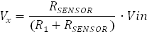

Figure 3. Sensor
application with divider circuit
Digital-to-Analog Converters
The next application
demonstrates how a voltage divider can be used to create a simple digital
–to-analog converter. The function of a
digital-to-analog converter, or DAC, is to convert digital data to analog voltage. The simplest architecture of a DAC can be
shown as a simple voltage divider, where a reference voltage is connected to a
string of equally sized resistors. The nodes of the resistor string display a
voltage that is related to the equivalent resistor-divider impedance of the
inspected node. An example of a simple
DAC is provided below.

No comments:
Post a Comment